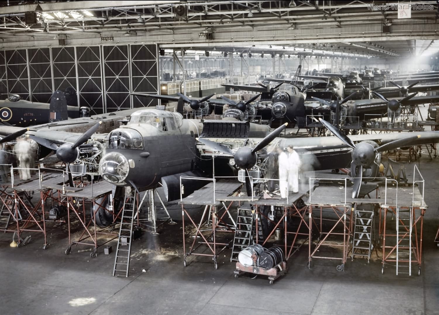
The mainplanes of the Lancaster are constructed on two main spars with U-section channel booms and plate webs. These booms are machined from 29-foot long extruded bars made of L40 (RR56) alloy. In the machine shop, the parts move longitudinally back and forth as they undergo various operations. Initially, the booms are channelled out using excellent Wadkin cutters, hydraulically clamped to beds. These clamps, which can be fitted by one person in seven minutes, are much more efficient compared to the 1.5 hours it takes two people with hand clamps. After being channelled, milled with a variable-angle cutter, and straightened, the booms are jig-drilled with the webs before assembly.
An interesting aspect of the shop is that fabrication stops at a certain point, beyond which all assembly, anodising, and treatment begins. Throughout fabrication, a machine loading system ensures each machine is loaded three operations ahead, saving time and closely monitoring material shortages.
The spars are then assembled in vertical jigs, with each wing worked on while standing upright on its trailing edge. Spar booms are bolted to the webs inside each spar, with the channel bolted through the bottom of the U. The wing’s centre section is integral with the fuselage’s centre section, followed by an outer wing panel on each side, with separate leading and trailing edges attached to the front and rear spars and separate wingtips. The wings now use top-hat-section chordwise stringers instead of the previously employed Z-section stringers. These top-hat stringers handle more compressive loads in the skin, which has been thickened to support the heavy-loaded weight.
Flush-riveting on the wings has been replaced by mushroom-headed rivets to prevent skin buckling during countersinking and flush-riveting by semi-skilled labour.
The assembled wing section has all equipment fitted before general assembly begins. Four welded steel tubular (T45) engine mountings are attached to the front spar, and undercarriage beams are added to the inner mountings. These beams, cast in DTD300 in one piece, replace about 50 fabricated parts used in the prototype. The only change for the installation of Hercules instead of Merlin motors is in the mountings forward of the undercarriage beams on the inner nacelles. The outer nacelles are identical to those of the Beaufighter II for the Merlin and Beaufighter I for the Hercules, highlighting cooperation in design.
As assembly progresses, various equipment is added. For example, the propeller de-icing fluid tank, made of transparent cellulose acetate, is slung behind the front spar in each inner nacelle. The oil tank, holding 42 gallons (37.5 gallons of oil space and 4.5 gallons of air space), is slung in front of the spar in each nacelle behind the fireproof bulkhead. Six fuel tanks are installed, the largest holding 585 gallons, with a total capacity of 2,158 gallons, equivalent to about 15,000 pounds of fuel.
